 Free JavaScript Editor
Ajax Editor
Free JavaScript Editor
Ajax Editor
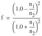
14.1. RefractionRefraction is the bending of light as it passes through a boundary between surfaces with different optical densities. You can easily see this effect by looking through the side of an aquarium or at a straw in a glass of water. Light bends by different amounts as it passes from one material to another, depending on the materials that are transmitting light. This effect is caused by light traveling at different speeds in different types of materials. This characteristic of a material is called its INDEX OF REFRACTION, and this value has been determined for many common materials that transmit light. It is easy to model refraction in our shaders with the built-in function refract. The key parameter that is required is the ratio of the index of refraction for the two materials forming a boundary where refraction occurs. The application can compute this ratio and provide it to the OpenGL shader as a uniform variable. Given a surface normal, an angle of incidence, and the aforementioned ratio, the refract function applies Snell's law to compute the refracted vector. We can use the refracted vector in a fragment shader to access a cube map to determine the surface color for a transparent object. Once again, our goal is to produce results that are "good enough." In other words, we're after a refraction effect that looks plausible, rather than a physically accurate simulation. One simplification that we make is that we model the refraction effect at only one surface boundary. When light goes from air through glass, it is refracted once at the air-glass boundary, transmitted through the glass, and refracted again at the glass-air boundary on the other side. We satisfy ourselves with simulating the first refraction effect. The results of refraction are complex enough that most people would not be able to tell the difference in the final image. If we go ahead and write a shader that performs refraction, we will likely be somewhat disappointed in the results. It turns out that most transparent objects exhibit both reflection and refraction. The surface of a lake reflects the mountains in the distance if you are looking at the lake from one side. But if you get into your boat and go out into the lake and look straight down, you may see fish swimming around underneath the surface. This is known as the FRESNEL EFFECT. The Fresnel equations describe the reflection and refraction that occur at a material boundary as a function of the angle of incidence, the polarization and wavelength of the light, and the indices of refraction of the materials involved. It turns out that many materials exhibit a higher degree of reflectivity at extremely shallow (grazing) angles. Even a material such as nonglossy paper exhibits this phenomenon. For instance, hold a sheet of paper (or a book) so that you are looking at a page at a grazing angle and looking towards a light source. You will see a specular (mirrorlike) reflection from the paper, something you wouldn't see at steeper angles. Because the Fresnel equations are relatively complex, we make the simplifying assumptions that (A) the light in our scene is not polarized, (B) all light is of the same wavelength (but we loosen this assumption later in this section), and (C) it is sufficient to use an approximation to the Fresnel equations rather than the exact equations themselves. An approximation for the ratio between reflected light and refracted light created by Christophe Schlick is
In this equation, V is the direction of view, N is the surface normal, and f is the reflectance of the material when q is 0 given by
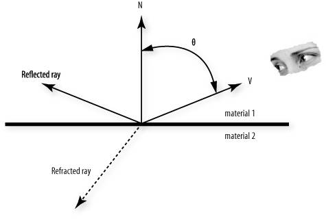
where n1 and n2 are the indices of refraction for materials 1 and 2. Let's put this together in a shader. Figure 14.1 shows the relevant parameters in two dimensions. For the direction of view V, we want to compute a reflected ray and a refracted ray. We use each of these to access a texture in a cube map. We linearly blend the two values with a ratio we compute using the Fresnel approximations described above. Figure 14.1. The geometry of refraction
In The Cg Tutorial, Randima Fernando and Mark Kilgard describe Cg shaders for refraction that can easily be implemented in GLSL. The code for our vertex shader is shown in Listing 14.1. The ratio of indices of refraction for the two materials is precomputed and stored in the constant Eta. A value of 0.66 represents a boundary between air (index of refraction 1.000293) and glass (index of refraction 1.52). We can allow the user to control the amount of reflectivity at grazing angles by using a variable for the Fresnel power. Lower values provide higher degrees of reflectivity at grazing angles, whereas higher values reduce this effect. The value for f in the equations above is also stored as a constant. (We could have the application provide Eta and FresnelPower as uniform variables. This would then require the application to compute and pass F as well.) The vertex shader uses the viewing position and the surface normal to compute a reflected ray and a refracted ray. The vertex position is transformed into eye coordinates. The reflect and refract functions both require an incident vector. This is just the vector going in the direction opposite of V in Figure 14.1. We compute this vector (i) by subtracting the viewing position (which is defined as being at (0, 0, 0) in the eye coordinate system) from the eye coordinate position and normalizing the result. We also transform the surface normal into the eye coordinate system and normalize it (n). To compute the angle q, we really need the vector V as shown in Figure 14.1 instead of i so that we can perform a dot product operation. We get this vector by negating i. We plug the values into the Fresnel approximation equation to get the ratio between the reflective and refractive components. The values for i and n are sent to the built-in functions reflect and refract to compute a reflected vector and a refracted vector. These are used in the fragment shader to access the environment map. The application that uses these shaders allows the environment map to be rotated independently of the geometry. This transformation is stored in one of OpenGL's texture matrices. The resulting rays must be transformed with this matrix to access the proper location in the rotated environment. Listing 14.1. Vertex shader for Fresnel reflection/refraction effect
The corresponding fragment shader is shown in Listing 14.2. All the hard work has been done in the vertex shader. All that remains for the fragment shader is to perform the two environment map lookups and to use the computed ratio to blend the two values. Listing 14.2. Fragment shader for Fresnel reflection/refraction effect
With a small modification, we can get our reflection/refraction shader to perform another cool effect, although we stray a bit further from realistic physics. As stated earlier, the refraction of light is wavelength dependent. We made the simplifying assumption that all our light was a single wavelength, and this allowed us to compute a single refracted ray. In reality, there would be a continuum of refracted rays, one for each constituent wavelength of the light source. The breaking up of a light source into its constituent components, for example, with a prism, is called CHROMATIC DISPERSION. In camera lenses, this effect is undesirable and is called CHROMATIC ABERRATION. We can model our light as though it contains three wavelengths of light: red, green, and blue. By providing a slightly different index of refraction for each of red, green, and blue, we can compute three slightly different refraction rays (see Listing 14.3). These three rays are passed to the fragment shader, where they perform three environment map accesses. The RefractR ray obtains just the red component of the final refracted color, and RefractG and RefractB obtain the green and blue components similarly. The result is used as the refracted color value. The remainder of the fragment shader is the same (see Listing 14.4). Listing 14.3. Vertex shader for chromatic aberration effect
Listing 14.4. Fragment shader for chromatic aberration effect
Results of these shaders are shown in Color Plate 17. Notice the color fringes that occur on the character's knee and chest and on the top of his arm. |
Ajax Editor
JavaScript Editor