 JavaScript Editor
JavaScript Debugger
JavaScript Editor
JavaScript Debugger
So far, we've used the Remoting infrastructure to communicate between applications. However, peer-to-peer applications often need to work at a lower level and take networking, sockets, and broadcasts into their own hands.
In this chapter, we'll cover the essentials of network programming with .NET. We'll start by reviewing the basics of physical networks and network protocols such as the Internet Protocol (IP), Transmission Control Protocol (TCP), and User Datagram Protocol (UDP), and then consider the support that's built into the System.Net namespace. We'll also present sample applications that demonstrate how you can stream data across a network with a TCP or UDP connection. All of this is in preparation for the peer-to-peer file-sharing application we'll develop over the next two chapters.
A network is defined simply as a group of devices connected by communication links. A traditional local area network (LAN) connects devices over a limited area, such as a company website or an individual's house. Multiple local area networks are connected into a wide area network (WAN) using a variety of technologies. In fact, the Internet is nothing more than a high-speed backbone that joins together millions of LAN networks.
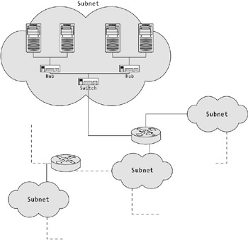
Networks are made up of four key physical components (not including the cabling), as described here:
A network interface card (NIC) is the adapter that connects a device to a LAN. In a personal computer, all traffic flows through the network card.
A hub connects multiple devices in a LAN. Essentially, traffic received by the hub is forwarded to every device connected to the hub.
A switch connects multiple hubs or devices. It works like a hub, but with intelligence. Traffic received by a hub is forwarded to a destination node based on a lookup table stored in the switch. In the past, switches were most often used to connect hubs, but the low cost of switches and their superior performance means that many modern networks connect devices directly to switches.
A router connects multiple subnets. Each subnet may consist of connected devices, hubs, and switches.
Figure 7-1 shows a sample network diagram that puts these parts into perspective.
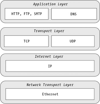
Programming tasks rarely require any understanding of the physical makeup of a network. What's much more important are the protocols used to encode information sent over a network link. Understanding the technology used to transfer information around a network can be difficult, because there are layers upon layers of different protocols that work in conjunction. At the transport level, most of the computers or devices connected to the network use the Ethernet Protocol. Ethernet defines the electrical signals that devices use to communicate on the wire. Other layers are built on top of the transport protocol, as shown in Figure 7-2.
This diagram simplifies life slightly by concentrating on the protocols with which you'll need to work when programming a peer-to-peer application. For example, it doesn't mention other network-level technologies for data linking, such as frame relay, or Internet-layer protocols such as the Internet Control Message Protocol (ICMP), which is used to manage and report errors between devices on a network and the Internet Group Management Protocol (IGMP), which is used to join multicast groups.
Each of the layers in Figure 7-2 plays a critical role in networking; you'll be introduced to them over the next few sections.
The Internet Protocol (IP) is an addressing protocol that's one of the cornerstones of the modern Internet. With IP, every device on a network is assigned a unique 32-bit (four bytes) numeric address, called the IP address. Usually, the address is represented in a dotted quad notation, as in 192.145.0.1. Each of these four values represents one byte of the IP address, and can thus be a number from 0 to 255.
According to IP, nodes on a network must send information using IP datagrams. Each datagram contains the actual data that's being sent and an IP header. The IP header is the important part—it allows the maze of switches and routers in between the source and the destination to direct the message appropriately. The IP header contains quite a bit of information, but the most important details are as follows:
The time to live (in hops). For example, if a message only has five hops to live, it can only cross five routers before it will be discarded. Of course, the IP packet might take several independent paths, each one of which will be limited to five hops.
The IP address of the device that sent the message.
The IP address of the device that should receive the message.
Of course, you'll never need to create an IP header or break your data into separate IP packets on your own because the .NET and Windows infrastructure will handle these lower-level tasks for you. In this book, we won't analyze the IP header in detail or explain how routers and subnets route and filter messages. There are numerous books dedicated to networking technology.
One less obvious fact about IP is that the IP address itself reveals some information about the device. Every IP address is made up of two pieces: a portion that identifies the network (and possibly the subnet of the network), and a portion that identifies the device in the network. The number of bytes allocated to each part depends on the type of network that's being used. Here's how it works:
If the first value in the IP address is from 1–126, it's a class A network address.
If the first value in the IP address is from 128–191, it's a class B network address.
If the first value in the IP address is from 192–223, it's a class C network address.
The difference between these types of networks is the number of nodes they can accommodate. Class A addresses are used for extremely large networks that can accommodate over 16 million nodes. With a class A network, the first byte in the IP address is used to define the network and the remaining three bytes identify the host. It's only possible to have 126 class A networks worldwide, so only extremely large companies such as AT&T, IBM, and HP have class A networks. Thus, in the IP address 120.24.0.10, the number 120 identifies the network and the remaining values identify the device.
Class B addresses use the first two bytes to describe the network. There can be about 16,000 class B networks worldwide, each with a maximum of 65,534 devices. Thus, in the IP address 150.24.0.10, the value 150.24 identifies the network, and the 0.10 identifies the device.
Finally, class C networks use the first three bytes to describe a network. That leaves only one byte to identity the device. As a result, class C networks can hold only 254 devices. Most companies that request an IP address will be assigned a class C IP address. If more devices are required, multiple class C networks can be used.
Note that this list leaves out some valid IP addresses because they have special meanings. Here's a summary of special IP addresses:
127.0.0.0 is a loopback address that always refers to the local network.
127.0.0.1 is a loopback address that refers to the current device.
IP addresses that start with a number from 224–239 are used for multicasting.
IP addresses that start with 240–255 are reserved for testing purposes.
Chapter 1 introduced the problem that the world is running out of IP addresses. In fact, there are already more devices connected to the Internet than there are available IP addresses. To compensate for this problem, devices that aren't connected to the Internet (or access the Internet through a gateway computer) can be given private IP addresses. Private IP addresses aren't globally unique. They're just unique within a network. All classes of networks reserve some values for private IP addresses, as follows:
In a class A network, any address beginning with 10 is private.
In a class B network, any address beginning with 172.16–172.31 is private.
In a class C network, any address beginning with 192.168.0–192.168.255 is private.
Of course, a computer that's sheltered from the Internet doesn't need to use a private IP address—just about any IP address would do. Unfortunately, computers without an IP address can be difficult or impossible to contact from another network. This is one of the headaches of peer-to-peer programming.
For a behind-the-scenes look at networking, you can use some of the commandline utilities that are included with the Windows operating system. One well-known utility is ping.exe, which contacts a device at a specified IP address using the ICMP protocol, and sends four test packets requesting a response. If the remote device receives the ping request, it will normally echo the packets back. Each packet is 32 bytes in size and is given 128 hops to live.
For example entering this at the command line:
ping 127.0.0.1
might elicit this response:
Pinging 127.0.0.1 with 32 bytes of data:

Reply from 127.0.0.1: bytes=32 time<1ms TTL=128
Reply from 127.0.0.1: bytes=32 time<1ms TTL=128
Reply from 127.0.0.1: bytes=32 time<1ms TTL=128
Reply from 127.0.0.1: bytes=32 time<1ms TTL=128

Ping statistics for 127.0.0.1:
    Packets: Sent = 4, Received = 4, Lost = 0 (0% loss),
Approximate round trip times in milli-seconds:
    Minimum = 0ms, Maximum = 0ms, Average = 0ms
The ping utility can be used to test if a remote host is online, although it may not succeed, depending on the firewall. For example, many heavily trafficked sites ignore ping requests because they're wary of being swamped by a flood of simultaneous pings that will tie up the server, thereby creating a denial-of-service attack.
To study the low-level communication in more detail, you can use an interesting utility called tracert.exe. It attempts to contact the host specified in the IP address, and indicates the route that was taken.
This tracert request simply uses the local loopback alias:
tracert 127.0.0.1
It receives the following unremarkable response:
Tracing route to localhost [127.0.0.1]
over a maximum of 30 hops:
  1 <1 ms <1 ms <1 ms localhost [127.0.0.1]
Trace complete.
The following tracert request, however, contacts a Microsoft web server. Note that we've used a domain name instead of the IP address. You can use either interchangeably with all of the command-line utilities discussed in this section. However, many IP addresses will not have a DNS entry (particularly if the computer isn't a web server).
tracert www.yahoo.com
Here's the result:
Tracing route to www.yahoo.akadns.net [64.58.76.177]
over a maximum of 30 hops:

  1 26 ms 23 ms 23 ms tlgw11.bloor.phub.net.cable.rogers.com
[24.114.131.1]
  2 23 ms 23 ms 24 ms 10.1.67.1
  3 26 ms 23 ms 23 ms gw02.bloor.phub.net.cable.rogers.com
[66.185.83.157]
  4 25 ms 23 ms 23 ms gw01.wlfdle.phub.net.cable.rogers.com
[66.185.80.6]
  5 28 ms 23 ms 24 ms gw02.wlfdle.phub.net.cable.rogers.com
[66.185.80.142]
  6 48 ms 47 ms 47 ms dcr1-so-3-1-0.NewYork.cw.net [206.24.207.85]
  7 51 ms 53 ms 53 ms dcr1-loopback.Washington.cw.net [206.24.226.99]
  8 52 ms 52 ms 53 ms bhr1-pos-0-0.Sterling1dc2.cw.net [206.24.238.34]
  9 51 ms 53 ms 52 ms csr03-ve242.stng01.exodus.net [216.33.98.219]
 10 57 ms 54 ms 52 ms 216.35.210.122
 11 55 ms 53 ms 53 ms www8.dcx.yahoo.com [64.58.76.177]

Trace complete.
In this case, 11 routers are crossed en route to the Yahoo! web server, which isn't bad! As with the ping test, a tracecert can fail if a firewall prevents it.
Another interesting utility is arp.exe, which can display the media access control (MAC) address and IP address of the current computer. (The MAC address is a unique hexadecimal value hard-coded in the network card.)
arp -a
And here's the command-line response:
Interface: 24.114.131.60 —- 0x10003
  Internet Address     Physical Address    Type
  24.114.131.1         00-00-77-95-5d-5b   dynamic
Alternatively, you can use ipconfig.exe to retrieve just IP information for the current computer.
Finally, you can use route.exe to determine how outgoing requests are routed from your computer. Enter the following at the command line to see a list of address ranges and where the request will be forwarded:
route print
In the display below, requests for the local computer (IP address 24.114.131.0) are routed to the loopback alias 127.0.0.1. All other requests are dispatched to the gateway at 24.114.131.60.
=========================================================================
Active Routes:
Network Destination        Netmask          Gateway        Interface  Metric
           0.0.0.0          0.0.0.0     24.114.131.1   24.114.131.60       30
     24.114.131.0  255.255.255.128    24.114.131.60   24.114.131.60      30
    24.114.131.60  255.255.255.255         127.0.0.1       127.0.0.1     30
   24.255.255.255  255.255.255.255    24.114.131.60   24.114.131.60     30
         127.0.0.0         255.0.0.0        127.0.0.1        127.0.0.1     1
         224.0.0.0         240.0.0.0   24.114.131.60    24.114.131.60    30
  255.255.255.255   255.255.255.255   24.114.131.60    24.114.131.60    1
Default Gateway:       24.114.131.1
=========================================================================
Persistent Routes:
  None
Transmission Control Protocol (TCP) and User Datagram Protocol (UDP) are two higher-level protocols that depend on IP. When you program an application, you won't create IP datagrams directly. Instead, you'll send information using TCP or UDP.
TCP is a connection-oriented protocol that has built-in flow control, error correction, and sequencing. Thanks to these features, you won't need to worry about resending information if a data collision occurs. You also won't have to worry about resolving any one of the numerous possible network problems that could occur as information is segmented into packets and then transported and reassembled in its proper sequence at another computer. As a result, TCP is a fairly complex protocol with a certain amount of overhead built-in. However, it's also the favorite of most network programmers, and it's the protocol we'll use to transfer files with the application developed in the next two chapters.
| Tip |
If an unrecoverable error occurs with TCP and retransmission cannot solve it, an error will be propagated up the stack until it appears in your code as a .NET exception.You can catch and respond to this exception accordingly. |
UDP is a connectionless protocol for transferring data. It doesn't guarantee that messages will be received in sequence, that messages won't be lost, or that only one copy of a given message will be received. As a result, UDP is quite fast, but it requires a significant amount of work from the application programmer if you need to send important data. One reason UDP might be used in a peer-to-peer application is to support peer discovery. This is because UDP allows you to send messages to multiple nodes on the network at once, without necessarily knowing their IP address. This is possible through broadcasting and multicasting, two technologies introduced later in this chapter.
Both TCP and UDP introduce the concept of ports. Port numbers don't correspond to anything physical—they're simply a method for differentiating different application endpoints on the same computer. For example, if you're running a web server, your computer will respond to requests on port 80. Another application might use port 8000. Ports map connections to applications.
Port numbers are divided into three categories:
Ports from 0–1023 are well-known system ports. They should only be used by a privileged system process (for example, part of the Windows operating system), not your application code.
Ports from 1024–49151 are registered user ports. Your server applications can use one of these ports, although you may want to check that your choice doesn't conflict with a registered port number for an application that could be used on your server.
Ports from 49152–65525 are dynamic ports. They're often used for ports that are allocated at runtime (for example, a local port a client might use when contacting a server).
The Internet Assigned Numbers Authority (IANA) assigns registered ports. For a list of defined port numbers, refer to http://www.iana.org/assignments/port-numbers.
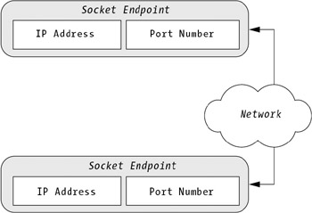
Remember, every transmission over TCP or UDP involves two port numbers: one at the server end and one at the client end. The server port is generally the more important one. It's fixed in advance, and the server usually listens to it continuously. The client port is used to receive data sent from the server, and it can be chosen dynamically when the connection is initiated. A combination of port number and IP address makes an endpoint, or socket, as shown in Figure 7-3.
Finally, it's worth noting that although only one application can use a port at a time, an application can serve multiple clients through the same port—in fact, with .NET, it's easy.
| Note |
An endpoint in a TCP connection is called a stream socket. An endpoint in a UDP connection is called a datagram socket. There's one other type of socket that we won't use in this book, which is the lower-level raw socket, which bypasses both TCP and UDP. |
Several higher-level protocols are common in the Internet world. These are called application protocols, and the interesting fact is that they're built on top of TCP or UDP.
For example, the File Transfer Protocol (FTP), Hypertext Transfer Protocol (HTTP), and e-mail protocols (SMTP, POP3, and IMAP) all use TCP to establish connections and send messages. They simply define a grammar of recognized messages. For example, FTP defines commands such as STOR (upload a file) and QUIT (close the connection). These commands, however, are nothing special— they're really just ASCII-formatted strings that are sent over a TCP connection. You could easily create your own FTP-like protocol by defining some string constants and relying on the TCP to perform all the heavy lifting.
Similarly, some application-level protocols are based on UDP. They include Trivial File Transfer Protocol (TFTP), Lightweight Directory Access Protocol (LDAP), and DNS (the protocol used to transfer domain name information). In this case, the low-bandwidth features of UDP are preferred to the connection-centric ones of TCP.
This brings our exploration of core networking concepts to a close. In the next section, you'll consider how these protocols are used in .NET code.
Free JavaScript Editor
JavaScript Editor